Quick answer
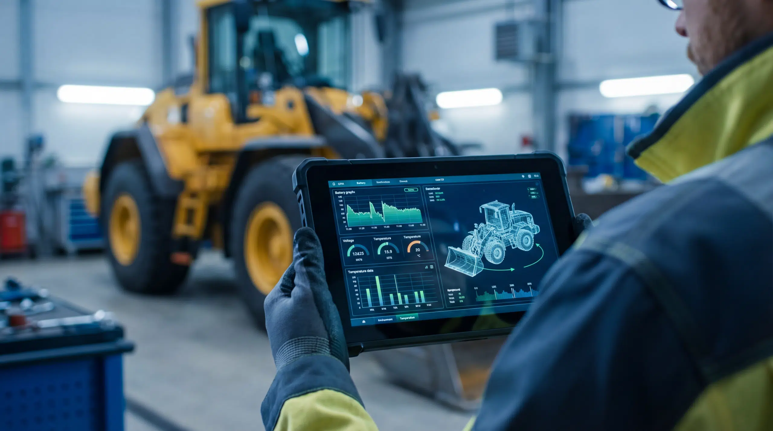
Battery thermal management (BTM) is the system that keeps battery cells inside their optimal temperature window during charging, discharging and standby. For heavy-duty EVs, BTM has to handle three regimes that exceed passenger-car practice: continuous high-power traction (300-800 kW for hours), megawatt fast-charging (1-3 MW peak heat dissipation), and extreme-environment operation (mining at -40 degrees C, port terminals at +50 degrees C). Three architectures dominate: indirect liquid cooling with cold plates (passenger-car standard, scaled), direct liquid cooling with cell-level coolant contact, and immersion cooling with dielectric fluid. Each makes different trade-offs in cooling capacity, weight, complexity and cost.
This article walks through what makes heavy-duty BTM different, what architectures are deployed today, and what the next generation of MCS-capable trucks demands.
Why heavy-duty BTM is not a scaled passenger-car system
The intuition is that a heavy-duty battery is just a passenger-car battery with more modules. The thermal reality is different. Three structural shifts make heavy-duty BTM its own problem.
Continuous traction load
A passenger car uses peak traction power for seconds at a time. A heavy-duty truck climbing a 4% grade at full GVW uses 400-600 kW continuously for tens of minutes. Cell-level losses at sustained C-rates are an order of magnitude higher in total energy than a passenger-car drive cycle. Cold-plate systems sized for passenger-car drive profiles run hot under heavy-duty traction.
Fast-charge heat at MCS power
A 1 MW charge into a 600 kWh pack means about 1.5 C charge rate. Internal cell losses at 1.5 C in modern NMC cells are 1.5 to 3 percent of charge power, depending on chemistry, SoC and cell temperature. That is 15-30 kW of heat over the charge duration, all of which has to leave the pack on a 20-30 minute timeline.
Operating-temperature extremes
Passenger cars target 0 to +35 degrees C ambient as their thermal-design envelope. Heavy-duty platforms operate from mining sites at -40 degrees C through port terminals at +50 degrees C, often within the same fleet. Pre-conditioning, heating and active cooling all have to handle a wider range, with longer transients (a heavy battery does not warm up quickly).
Three BTM architectures, side by side
Heavy-duty platforms today use one of three thermal architectures, sometimes hybridized. The choice is rarely just thermal; it interacts with packaging, weight, complexity, cost and fast-charge capability.
| Architecture | How it works | Cooling capacity | Trade-off |
|---|---|---|---|
| Indirect liquid (cold plates) | Coolant flows through plates pressed against the cells | ~1-3 W/cm-squared cell surface | Standard, well-understood; thermal gradient cell-to-cell limits fast-charge headroom |
| Direct liquid (cell-level coolant) | Coolant flows through channels between or around individual cells | ~3-6 W/cm-squared cell surface | Higher capacity; integration cost and sealing complexity rise; water-glycol leakage is a fault |
| Immersion (dielectric fluid) | Cells sit submerged in non-conductive fluid (mineral oil, fluorocarbon, ester) | 5-10+ W/cm-squared cell surface | Best thermal performance, lowest cell-to-cell gradient; mass penalty, fluid cost, regulatory novelty |
For passenger cars, indirect liquid (cold plates) covers the use case at acceptable cost. For heavy-duty vehicles below ~500 kWh battery and below ~500 kW peak charge, indirect liquid still works. Above those thresholds, direct liquid and immersion become structurally necessary, not just optional.
What MCS does to thermal design
The transition from CCS2 (350 kW typical) to MCS (1.0-1.5 MW first generation, 3 MW second generation) is the single biggest forcing function in heavy-duty BTM today. Three things change.
1. Peak heat load triples or quadruples
At 1 MW charge power and 2% internal loss, the pack has to reject 20 kW. At 3 MW and 2% loss, that becomes 60 kW. Cooling-system mass flow rate, heat-exchanger size, and chiller capacity all scale up proportionally. An MCS-capable thermal system is heavier and more complex than its CCS2 equivalent.
2. Cell-to-cell uniformity becomes critical
At low C-rates, cells in a pack equilibrate naturally. At MCS C-rates of 1.5 to 3 C, individual cell temperature differences of 5-8 degrees C between hot and cold cells cause measurable capacity walk-down within months. Fast-charge readiness requires cell-to-cell gradients below 3-4 degrees C, which is hard with cold plates and natural for immersion.
3. Pre-conditioning becomes mandatory
Charging a battery at 1 MW from a cold start (cells below 10 degrees C) is impossible without lithium plating risk. The vehicle has to pre-condition the pack to 25-35 degrees C before the charge starts. This takes 20-40 minutes from cold ambient and consumes 5-10 kWh, which has to be planned into the operational cycle.
Where the cooling fluid matters
Cooling-medium choice is a separate axis from architecture. The same cold-plate or direct-liquid architecture can run on water-glycol, on a fluorinated dielectric (3M Novec, replaced by alternatives), on a hydrocarbon dielectric ester, or on a refrigerant-based two-phase system.
- Water-glycol is the dominant choice for indirect liquid systems. Mature, low-cost, well-understood. Limited by single-phase heat transfer and the need to keep the coolant electrically isolated from the cells.
- Dielectric ester (immersion) is the leading choice for new heavy-duty immersion designs. Compatible with cells, lower environmental impact than fluorinated alternatives, but heavier than water-glycol and more expensive.
- Refrigerant-based two-phase uses the latent heat of phase change to absorb very high heat loads in compact volumes. Highest performance, most complex packaging, regulatory complexity from refrigerant handling.
Heating in cold environments
Most BTM discussion focuses on cooling, but heating is at least as important for heavy-duty platforms operating in cold climates. A pack at -20 degrees C cannot deliver full traction power and cannot accept fast charge. Heating strategies include:
- Resistive PTC heaters in the coolant loop. Simple, fast, but consume traction battery energy.
- Heat-pump systems sharing thermal load with the cabin. Two to three times more efficient than resistive heating but adds complexity.
- Self-heating via internal AC excitation. Uses cell internal resistance to dissipate heat directly inside the cells. Very fast warm-up but limited to specific cell chemistries and BMS firmware that supports it.
- Pre-heating from grid power during plug-in standby. Off-board energy is essentially free thermally; charging stations near the home depot can pre-condition the pack before the driving day starts.
Integration challenges that surface late
BTM is rarely the cause of program delays in heavy-duty zero-emission projects. But it is often the system that makes other delays worse. Three common patterns:
- Cold-plate sized for traction, undersized for fast charge. The thermal team validates BTM against drive-cycle load profiles, then the program adopts MCS, and the existing cold plates cannot handle the new charge load. Re-sizing is a battery-pack repackage, often a year of rework.
- Coolant routing creating EMC coupling. Coolant lines run alongside HV cables. Conductive coolant (water-glycol) creates a parasitic path for common-mode currents. EMC tests fail at frequencies where the design team did not expect coupling.
- Pre-conditioning energy not in the operational model. Fleet operations planning assumes the vehicle is ready for fast charge on plug-in. In cold conditions it is not. Real-world cycle times grow by 20-40 minutes per charge, which compounds across a fleet day.
Where integration partners add value
BTM integration is the kind of work where the difference between a good and a poor design only shows up at month 18, in chamber testing or first hot-weather field trial. The high-leverage moments are early.
- Thermal architecture selection in concept phase, with MCS, traction profile and operating environment in scope from the start.
- Cell-to-coolant interface design, where most cell-to-cell uniformity battles are won or lost.
- Pre-conditioning strategy, including grid-side integration with depot infrastructure.
- EMC interaction testing, since coolant routing and HV harness layout share physical space.
An OEM that buys BTM as a Tier-1 module gets a thermal solution. An OEM that co-develops BTM with an integration partner gets a thermal solution that fits the rest of the vehicle, including the EMC, packaging, and operational model.
Frequently asked questions
What temperature range should a heavy-duty EV battery operate in?
Most heavy-duty Li-ion packs operate optimally between 15 and 35 degrees C cell temperature. Above 45 degrees C, calendar aging accelerates and fast-charge capability drops. Below 5 degrees C, charging becomes risky due to lithium plating, and traction power drops noticeably. BTM design targets keeping cells inside the 15-35 degrees C window across the vehicle’s full operating envelope.
What is the difference between indirect and direct liquid cooling?
Indirect liquid cooling uses a coolant flowing through cold plates that contact the cells externally. Direct liquid cooling routes coolant in channels that contact each cell or small cell groups directly. Direct liquid achieves higher cell-to-cell temperature uniformity at the cost of more complex sealing and integration. Most passenger-car packs use indirect; heavy-duty packs at MCS power increasingly need direct or immersion cooling.
Is immersion cooling viable for production heavy-duty batteries?
Yes, with caveats. Several heavy-duty mining and off-highway programs have moved to immersion-cooled packs in 2025-2026, citing both thermal performance and fire-safety benefits. Cost and weight remain higher than indirect liquid systems, and regulatory acceptance under ECE R100 isolation requirements requires careful documentation of dielectric fluid behavior under fault. For high-power or harsh-environment applications, the trade-offs increasingly favor immersion.
How does fast-charging affect battery thermal management design?
Fast-charging at MCS power levels (1 MW plus) typically dissipates 15-30 kW of heat into the pack over a 20-30 minute charge. This is several times the thermal load of normal traction operation. Thermal systems sized for traction often cannot handle fast-charge heat, requiring uprated chillers, higher coolant flow rates, or a switch to more capable architectures (direct liquid or immersion). Pre-conditioning the pack to 25-35 degrees C before charging is also required to enable safe fast charge from low ambient.
Designing a thermal system for an MCS-capable platform?
IntegratR’s thermal and integration teams work with OEMs from architecture review through chamber-level validation. Talk to us about your battery and thermal program.
 English
  Dutch
Dutch